
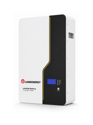
LIANKENERGY 51.2V 200Ah LiFePO4 battery. Charging parameters must come from the current product manual.
A LiFePO4 battery should be charged from the limits in its own manual, not from a voltage copied from another product. Match the charger to the battery voltage, allowed current, temperature range and BMS (battery management system) control method, then verify the result during a monitored charge.
Safety note: A stationary battery can deliver dangerous fault current even when it appears discharged. Isolate unrelated sources and loads before changing wiring. Use properly rated protection and insulated tools. Stop if the enclosure is swollen, leaking, unusually hot, mechanically damaged or giving an abnormal odour. High-voltage systems and internal battery work belong with qualified personnel.
The Four Items That Must Agree
Correct charging depends on four parts of the system agreeing with one another. In a solar or backup system, an inverter/charger, solar controller and DC charger may all feed the same bank, so you must check their combined effect rather than one device at a time.
|
Item |
What must match |
What a mismatch can cause |
|
Battery limits |
Charge voltage, maximum current, temperature and connection rules |
BMS trips, incomplete charging, heat or shortened service life |
|
Charger profile |
Chemistry, voltage stages, current limit and prohibited modes |
Overvoltage, repeated cut-off or a battery that never reaches its completion condition |
|
BMS control |
Charge permission, alarms, contactor or communication path |
A charger may continue after the battery asks it to stop |
|
Installation |
Cable size, fuse, terminal condition and all active charge sources |
Voltage drop, hot connections or more total current than expected |
The BMS is a protection layer. It should not be treated as the device that makes an incorrect charger safe. A well-configured system keeps normal charging inside the battery limits so that the BMS intervenes only when conditions become abnormal.
How LiFePO4 Charging Works
LiFePO4 batteries are commonly charged with a constant-current and constant-voltage process, often shortened to CC/CV. Constant current means the charger holds current near a set limit while voltage rises. Constant voltage means the charger then holds the target voltage while current falls.
During the constant-current stage, the charger supplies its permitted current while battery voltage rises. Once the configured charge voltage is reached, the charger holds that voltage and the current falls. The battery manufacturer may define completion by time, tail current (the low current remaining near the end of charging), BMS status or a combination of these conditions.
Names on charger menus can be confusing. One device may call the first stage bulk (the main high-current charging stage) and the next stage absorption (the controlled-voltage stage near full charge). Another may use charge voltage and CV time. The label matters less than what the charger actually does.
Do not assume that every lead-acid stage belongs in a LiFePO4 profile. Equalisation (a deliberate high-voltage maintenance stage for some lead-acid batteries), desulfation (a lead-acid recovery mode that may use voltage pulses) and automatic high-voltage recovery modes are normally unsuitable unless the battery manufacturer explicitly permits them. Cold-weather voltage compensation designed for lead-acid batteries may also raise voltage in the wrong way for a LiFePO4 system.
How to Charge a LiFePO4 Battery Correctly
Step 1: Confirm the Exact Battery Limits
Start with the current manual or datasheet for the exact battery model. “12V lithium” or “48V LiFePO4” is not enough information. Record the following values before opening the charger menu:
- nominal battery or bank voltage and the number of batteries in series;
- permitted charge-voltage range or the required bulk and absorption value;
- recommended and maximum continuous charge current;
- absorption time, tail-current rule or other completion condition;
- float or standby voltage (the lower voltage a charger may hold after the main charge), or whether float should be disabled;
- minimum and maximum charging temperature;
- equalisation and temperature-compensation instructions;
- BMS communication, charge-enable or contactor requirements; and
- special rules for batteries connected in series or parallel.
If the manual and charger use different terms, map the function rather than guessing from the name. Ask the battery supplier to confirm any field that cannot be mapped.
The published values for one manufacturer are not a general LiFePO4 standard. For example, Victron specifies 14.2 V absorption and 13.5 V float for its 12.8 V Lithium Smart battery, while Battle Born publishes a 14.2 to 14.6 V bulk/absorb range and a float setting at or below 13.6 V for its own 12 V products. Both sources tell users to follow product-specific limits. This difference is exactly why a copied online number is not a commissioning method.
What the LIANKENERGY Brochure Already Tells Us
LIANKENERGY’s current brochure provides model-specific starting points for the E-STONE family. Keep the labels exactly as published until the model manual or engineering team confirms how each field maps to the charger menu.
|
Brochure model |
Rated energy |
Nominal voltage |
“Supply Voltage” in brochure |
“Output Current” in brochure |
Communication |
|
E-STONE 5.1 |
5.32 kWh |
51.2 V |
45.6–56.16 V |
100 A / 50 A |
CAN / RS485 / RS232 |
|
E-STONE 10.5 |
10.65 kWh |
51.2 V |
45.6–56.16 V |
200 A / 100 A |
CAN / RS485 / RS232 |
|
E-STONE 16.0 |
15.97 kWh |
51.2 V |
45.6–56.16 V |
300 A / 150 A |
CAN / RS485 / RS232 |
|
E-STONE 10.5 Pro |
10.65 kWh |
51.2 V |
45.6–56.16 V |
200 A / 100 A |
CAN / RS485 / RS232 / Wi-Fi |
|
E-STONE 16.0 Pro |
15.97 kWh |
51.2 V |
45.6–56.16 V |
300 A / 150 A |
CAN / RS485 / RS232 / Wi-Fi |
These entries prove that LIANKENERGY models do not all share one current rating. They do not by themselves tell an installer which number is the recommended charge current, the maximum continuous charge current or the charger’s constant-voltage setting. Those assignments still need the exact manual or written engineering confirmation.
The brochure also does not show a separate specification page clearly matching the 51.2 V 200 Ah product image used with this article. Do not transfer an E-STONE value to that pictured product simply because both use a 51.2 V nominal system.
Step 2: Inspect the Battery and Installation
Do not energise the charger until the battery and current path have passed a basic inspection.
1. Confirm polarity at the battery and charger.
2. Check that the charger voltage class matches the battery bank.
3. Inspect terminals, cables, isolators, fuses and busbars for looseness, corrosion, heat damage or an underrated component.
4. Verify that series and parallel connections follow the battery manual.
5. Measure battery temperature, not only room temperature.
6. Review the BMS for active high-voltage, low-voltage, over-temperature, low-temperature or communication alarms.
7. Identify every device that may charge the bank during the test.
A system can contain more charge sources than the installer first expects. Solar MPPT controllers, inverter/chargers, AC chargers, DC-to-DC chargers and regenerative equipment may share the same battery bus. List them all before calculating current.
Step 3: Choose a Compatible Charging Source
A suitable charger must do more than produce a voltage higher than the battery voltage. It must hold the correct profile under the actual load and stop or reduce charging when the battery requires it.
AC Charger or Inverter Charger
Use a LiFePO4 preset only after comparing its hidden values with the battery manual. If the preset cannot be inspected, a programmable custom profile is easier to verify. Confirm how the unit behaves after AC returns, after a BMS trip and while it is powering loads.
Solar Charge Controller
The panel does not connect directly to the battery. An MPPT or other suitable controller must regulate voltage and current. Check the controller output rating, its LiFePO4 settings, low-temperature logic and the maximum photovoltaic input permitted by the controller.
Alternator or Variable DC Source
Use a system designed to control current between the source and the LiFePO4 bank. A DC-to-DC charger (a device that takes variable DC input and delivers a controlled battery-charging profile) can limit current and separate the charge profile from alternator voltage. Confirm that the source and wiring can tolerate sustained charging and that a BMS disconnect will not expose the charging equipment to an unsafe condition.
Bench Power Supply
A current-limited power supply is not automatically a complete battery charger. It may lack temperature protection, charge termination, reverse-polarity protection and BMS integration. Use it only when the battery procedure explicitly allows it and a qualified person supervises the process.
Step 4: Enter Voltage Time and Current Settings
Transfer the approved battery values into every active charger. Record the old settings before changing them so that an incorrect change can be traced and reversed.
Charge Voltage
Use the battery manufacturer’s specified voltage at the battery terminals. A charger display can show its own output voltage while cable drop leaves a different voltage at the battery. Measure both points during charging if the cable run is long, current is high or the system has unexplained early termination.
Charge Current
The safe current limit is the lowest applicable limit in the complete path. Consider the battery, BMS, contactor, fuse, cable, connector and charger. For a bank with several chargers, add the maximum current that can arrive at the same time.
Charge rate is often expressed as C-rate (charge current divided by the battery’s rated amp-hour capacity):
Charge rate (C) = charge current (A) / rated capacity (Ah)
For a 200 Ah battery, 100 A equals 0.5C. This is a calculation, not approval to use 100 A. The product manual must permit that current, and parallel batteries must share current as designed.
Absorption Time and Completion
Set the duration or tail-current rule required by the battery. Too little time may prevent balancing or SOC synchronisation in systems that perform those functions near the top of charge. Excessive high-voltage hold time is not a substitute for fixing imbalance or a poor connection.
Float and Standby
Some LiFePO4 systems disable float; others use a lower standby voltage. Follow the battery and charger integration instructions. Do not copy a lead-acid float value merely because the charger requires something in the field.
Equalisation and Temperature Compensation
Disable equalisation, desulfation and pulse-recovery modes unless the battery manufacturer gives a documented procedure. Follow the LiFePO4 battery instructions for voltage temperature compensation. A lead-acid algorithm that increases charge voltage as temperature falls can conflict with the battery’s low-temperature protection.
Step 5: Connect the BMS to Every Charge Source
In a managed battery system, the BMS may communicate through CAN or RS485 (two common digital links used to exchange battery status and limits), open a charge-enable circuit, drive a relay or operate a contactor (an electrically controlled switch designed for higher current). Confirm which device has final authority to stop charging.
The important test is functional. Create only the safe test conditions permitted by the manufacturer, then verify that every charger responds to a charge-disable command or simulated limit as intended. A communication icon on the screen does not prove that charge control works.
Where chargers cannot communicate directly, the design may need a properly rated relay, contactor or remote on/off input. Do not interrupt high DC current with a small signal relay, and do not bypass the BMS to prevent nuisance trips. Repeated trips indicate that settings, cell balance, temperature, wiring or equipment compatibility needs investigation.
Step 6: Check Temperature Before Charging
Charging temperature is a product limit, not a weather guess. Measure the battery or cell temperature where the manufacturer specifies it.
Low-temperature behaviour varies by product. Victron’s Lithium Smart manual permits charging from 5°C to 50°C for the models covered by that manual. RELiON publishes different low-temperature rules for some of its products and offers self-heated models. These are product examples, not interchangeable limits.
For LIANKENERGY’s listed E-STONE and POWER PILE products, the brochure gives a general operating-temperature range of −20°C to 60°C and states that charge/discharge derating occurs from −10°C to 5°C and from 45°C to 55°C. This is useful evidence that temperature changes permitted power. It is not, however, a complete charger instruction: the brochure does not separately define the minimum full-current charging temperature, the reduced current or the BMS cut-off for every model. Confirm those values in the exact model manual before charging near either temperature boundary.
If the battery is below its permitted charging temperature:
- stop or inhibit charging;
- allow the battery to warm in a controlled way approved by the manufacturer;
- verify that any self-heating system has completed its warm-up sequence; and
- confirm that the BMS and charger agree before current reaches the cells.
Do not warm a battery with an uncontrolled heat source. A warm room sensor does not prove that cold cells inside a large pack are ready to charge.
Step 7: Run a Monitored First Charge
The first full charge after installation or a material settings change should produce a commissioning record.
1. Start from a known SOC (state of charge, the estimated percentage of energy remaining) range if the manual specifies one.
2. Enable one charging source first when practical.
3. Record charger output voltage and current.
4. Measure voltage at the battery terminals under load.
5. Watch pack voltage, cell-voltage spread, temperature, BMS limits and alarms.
6. Add other charge sources one at a time and confirm the total current.
7. Observe the transition from constant current to constant voltage.
8. Confirm that charge current tapers or charging ends according to the approved rule.
9. Check terminals, cables and protective devices for abnormal heating.
10. Save screenshots, event logs and final settings.
Stop the test if the battery heats abnormally, swells, smells unusual, repeatedly disconnects, shows a cell racing to the high-voltage limit or exceeds a documented boundary. Do not repeatedly reset the alarm to force the charge to finish.
How Long Charging Should Take
The nameplate current alone does not give the real charging time. Use the net current entering the battery and add time for the constant-voltage stage, balancing and any charger derating (automatic reduction of output because of temperature, input power or another limit).
Estimated bulk time (hours) = capacity to replace (Ah) / average net charge current (A)
Suppose a 200 Ah battery moves from 30% to 90% SOC. The nominal capacity to replace is 120 Ah. If the approved charger supplies 50 A and system loads are negligible, the calculated bulk portion is about 2.4 hours. The full process will take longer because current may taper and the charger may be derated by temperature or input power.
If the same system carries a 15 A DC-equivalent load while the charger supplies 50 A, only about 35 A reaches the battery. The bulk estimate becomes roughly 3.4 hours. This is why a battery can appear to charge slowly even when the charger is working correctly.
Use this estimate for planning, then confirm it with measured current. Do not promise a charging time from a theoretical maximum current that the installation cannot sustain.
Charging Several Batteries Together
For parallel batteries, confirm the permitted number of units, cable layout, overcurrent protection and current sharing method. Start with batteries at compatible voltages and states of charge as required by the manufacturer. Large differences can cause high equalisation current as soon as the connection is made.
For series batteries, follow the product’s explicit series-connection and balancing rules. A charger that sees only total bank voltage may not reveal one battery or cell reaching its limit early. Some drop-in batteries prohibit series use or require model-specific communication.
Do not assume that multiplying a single-battery voltage is the only setting change. BMS architecture, monitoring, charger isolation and fault handling can change with the bank configuration.
Why a LiFePO4 Battery May Not Charge
Use the symptom to decide what to measure next.
|
Symptom |
Evidence to check |
Likely direction |
|
Charger shows on but battery current is near zero |
Battery temperature, BMS charge permission, charger stage and terminal voltage |
Temperature lockout, BMS protection, full battery or wrong voltage target |
|
Charger output is correct but battery voltage is lower |
Voltage at charger, busbar (the common metal conductor that joins high-current circuits) and battery under current; cable and fuse temperature |
Cable drop, poor terminal, undersized conductor or damaged protection device |
|
Charging stops at a repeatable high SOC |
Highest cell voltage, cell spread, absorption time and event log |
Cell imbalance, settings mismatch or BMS high-cell protection |
|
SOC stays below 100% after charge current ends |
Shunt calibration, full-charge detection and BMS synchronisation |
Display or synchronisation issue rather than missing capacity |
|
Charging is much slower than expected |
Charger input power, active loads, derating and combined current |
Net current is lower than charger nameplate current |
|
Solar charging starts and stops |
Irradiance, PV input, controller limits, battery voltage and BMS status |
Variable solar input, controller configuration or BMS intervention |
|
Battery reads very low or zero terminal voltage |
BMS state, manual recovery procedure and physical condition |
Low-voltage protection or severe discharge; contact the supplier before recovery |
Do not bypass the BMS, open a sealed pack or apply an uncontrolled recovery voltage. A deeply discharged battery may require a model-specific wake-up or recovery procedure. If that procedure is not in the manual, stop and contact the supplier.
Common Charging Mistakes
Copying One Voltage From the Internet
A voltage without the battery model, series count, temperature, current and completion rule is incomplete. Use the current product manual and record the approved value beside the charger setting before you energise the system.
Counting Only One Charger
An inverter/charger and MPPT controller can operate together. Their combined current may reach the battery even when each device is individually below the limit. List every active source, add the maximum currents that can overlap and set limits so the total remains within the lowest approved system limit.
Treating Every BMS Trip as a Battery Defect
A BMS trip can be a correct response to wrong charger settings, cold cells, a hot terminal, communication loss or one high cell. Save the event data, remove the triggering condition and verify the settings before you reset it. Stop repeated resets if the same event returns.
Using a Lead Acid Recovery Mode
Equalisation and desulfation can command voltages or pulses outside the approved LiFePO4 profile. Disable them unless the battery manufacturer documents their use. If the charger cannot disable these modes, replace it with a compatible unit rather than relying on the BMS to catch every event.
Estimating Charging Time From Charger Current Alone
Loads, cable loss, source limits and the constant-voltage stage reduce net charging current. Measure current at the battery, subtract active loads and include taper time before you judge the result.
Changing Several Settings at Once
If the system improves or fails after five simultaneous changes, the cause remains unknown. Record the baseline, change one controlled group of settings and verify the result. Restore the last known safe configuration if behaviour becomes worse.
The Commissioning Record to Keep
Save enough information to reproduce the result later:
|
Field |
Record |
|
Battery model and serial number |
Exact identification and installation date |
|
Bank configuration |
Series and parallel arrangement |
|
Charger sources |
Model, firmware and connection method |
|
Approved charge limits |
Voltage, current, time, temperature and float rule |
|
BMS integration |
CAN, RS485, enable line, relay or contactor |
|
Starting condition |
SOC, voltage, cell spread and battery temperature |
|
Charge data |
Current, voltage, duration, active loads and source power |
|
Ending condition |
SOC, current taper, cell spread, temperature and alarms |
|
Physical checks |
Terminal and cable temperature, noise, smell and enclosure condition |
|
Final decision |
Accept, adjust settings, repair installation or escalate |
This record turns the first successful charge into a baseline. When charging later becomes slower or starts stopping early, you can compare the same measurements instead of relying on memory.
When to Contact the Battery Supplier
Stop configuration work and contact the supplier when the manual is missing, charger fields cannot be mapped, the BMS repeatedly blocks charging, one cell reaches its limit early, the enclosure or terminals heat abnormally, or a deeply discharged battery requires recovery.
Before requesting support, prepare the battery model and bank arrangement, system voltage, every charging-source model, maximum combined current, battery temperature range, required charging window and active load during charging. These details let the supplier diagnose the system instead of guessing from the battery’s Ah rating.
Final Thoughts
Correct LiFePO4 charging starts with the exact battery limits and ends with a monitored test that proves the whole system follows them. If charging is slow or stops early, save the BMS event, measure terminal voltage, net current and temperature before replacing parts. LIANKENERGY can review these project details and help match a stationary battery configuration with the inverter, charging sources and required charging window.
Frequently Asked Questions
Can I Use a Lead Acid Charger for a LiFePO4 Battery?
Only if the battery manufacturer permits it and the charger’s actual voltage, current, stage timing and shutdown behaviour match the LiFePO4 requirements. Equalisation, desulfation and incompatible temperature compensation must not run. A charger with a verified LiFePO4 or programmable profile is easier to commission.
What Voltage Should I Use to Charge a LiFePO4 Battery?
Use the voltage stated for the exact battery model and bank configuration. There is no single correct pack voltage for every LiFePO4 product. Series cell count, BMS limits, balancing strategy and charger termination all matter. Do not transfer a 12 V battery setting to a 24 V or 48 V bank by assumption.
What Charging Current Is Best for a LiFePO4 Battery?
Use the manufacturer’s recommended current and remain below every lower limit in the battery, BMS, cable, connector, fuse and charger path. Add currents from all chargers that can run together. A C-rate calculation helps compare current with capacity, but it does not replace product approval.
Can a Solar Panel Charge a LiFePO4 Battery Directly?
No. The solar array should feed a compatible charge controller that regulates voltage and current for the battery. Configure the controller from the battery manual and verify low-temperature control, output-current limits and BMS integration.
Can I Charge a LiFePO4 Battery Below Freezing?
Only when the exact battery documentation allows it and the required current reduction, internal heating or BMS control is active. Product rules differ. If the battery is below its permitted charge temperature, inhibit charging and follow the manufacturer’s warming procedure.
Why Does My LiFePO4 Battery Stop Charging Before 100 Percent?
Possible causes include SOC monitor drift, a short absorption period, cell imbalance, temperature protection, a high-cell BMS limit, charger derating, active loads or voltage drop. Check charge current, battery-terminal voltage, cell data and the BMS event log before concluding that capacity is missing.
Should a LiFePO4 Charger Stay Connected All the Time?
That depends on the battery manual, charger standby behaviour and application. Some systems use a lower float or standby voltage, while others disable float. Backup systems may remain connected for availability, but the settings must avoid an unapproved continuous high-voltage hold.
Technical References
- LIANKENERGY, Shandong Lianhe Energy Brochure — E-STONE and POWER PILE model data, published voltage/current field labels, communication interfaces, operating-temperature range and derating note; use only with the matching model and current revision.
- Victron Energy Lithium Battery Smart Manual technical data
— model-specific voltage, current and operating-temperature limits. - Victron Energy Lithium Battery Smart charging settings
— charger compatibility, absorption, float, current and temperature-compensation guidance for Victron products. - RELiON charging guidance
— product-specific charging, temperature, series/parallel and charger-source guidance. - Battle Born LiFePO4 charging guidance
— product-specific bulk, absorption and float settings illustrating why values differ by manufacturer.
Apply the guidance to your system
Share the load, capacity target, inverter model and installation conditions for a practical review.